Select the number of layers:
* Required fields


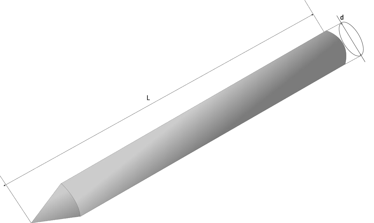
For Pile with circular section
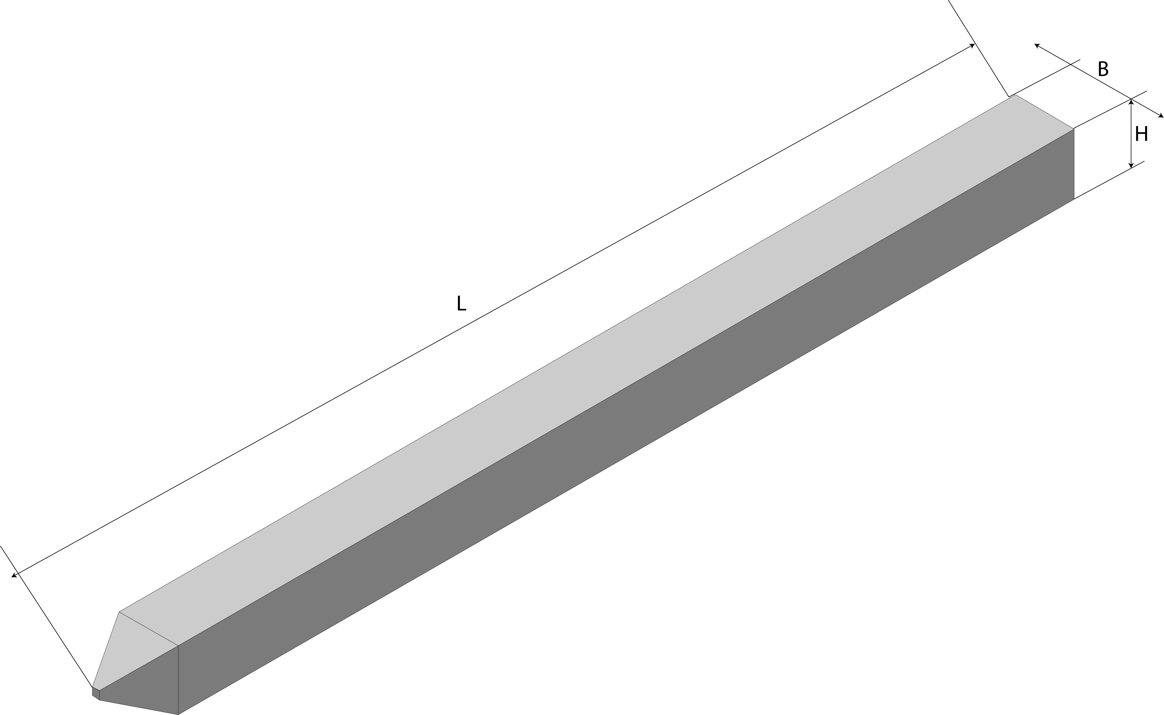
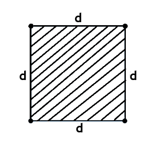
For Pile with square section
Get results by mail
* Required fields
Pile calculation program (According to NP 123: 2010)
This norm applies to the design of foundations on piles, respecting the condition: the side or diameter of the current cross section of the pile, d, is: 0.3 < d: S 3.0m.
The provisions of this norm are correlated with the provisions of the system of European construction standards - EUROCODES.
This normative is in accordance with the principles set out in Section 7 of SR EN 1997-1: 2004 and SR EN 1997-1: 2004 / NB: 2007, and as the case may be, with the associated errors and amendments.
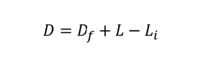
The consistency index Ic as a function of which the value of the soil can be determined inside the plasticity range, is defined by the following relation: Ic = (WL-W) / Ip, where W-represents the moisture of the soil sample in its natural state, WL-upper limit of plasticity, Ip-index of plasticity
1. Input data:
Layer characteristics {{index+1}}:
Layer thickness
H S,{{index+1}}
m
The volumetric weight of the layer
Y K,{{index+1}}
KN / m3
Soil type
Soil type
Consistency index
l C,{{index+1}}
2. Pile characteristics:
Depth of screed foundation

m
Recessed length of the pile in the radier

m
The length of the pile part included in the reinforced concrete screed is determined depending on the type of load and the type and diameter of the longitudinal reinforcement in the pile body (the leveling layer of concrete is not included in the screed thickness) according to specific technical regulations. In the case of foundations on piles subjected to axial stresses and horizontal forces that can be taken over by piles considered articulated in the raft, the piles must enter the raft with their heads intact on a length of 5 cm, and the longitudinal reinforcements of the piles in the screed at least 25 cm.
In the case of foundations on piles subjected to axial stresses or high horizontal forces, which require their taking over by piles considered embedded in the screed, the piles must enter the screed with intact ends at a length of at least 10 cm, and the longitudinal reinforcements of the piles must be embedded in the radier on a length determined by its constructive calculation, in compliance with the provisions of the technical norms.
Pile length:

m
Pile diameter:
Pile with circular section
d
m
Pile with square section (side width)
B
m
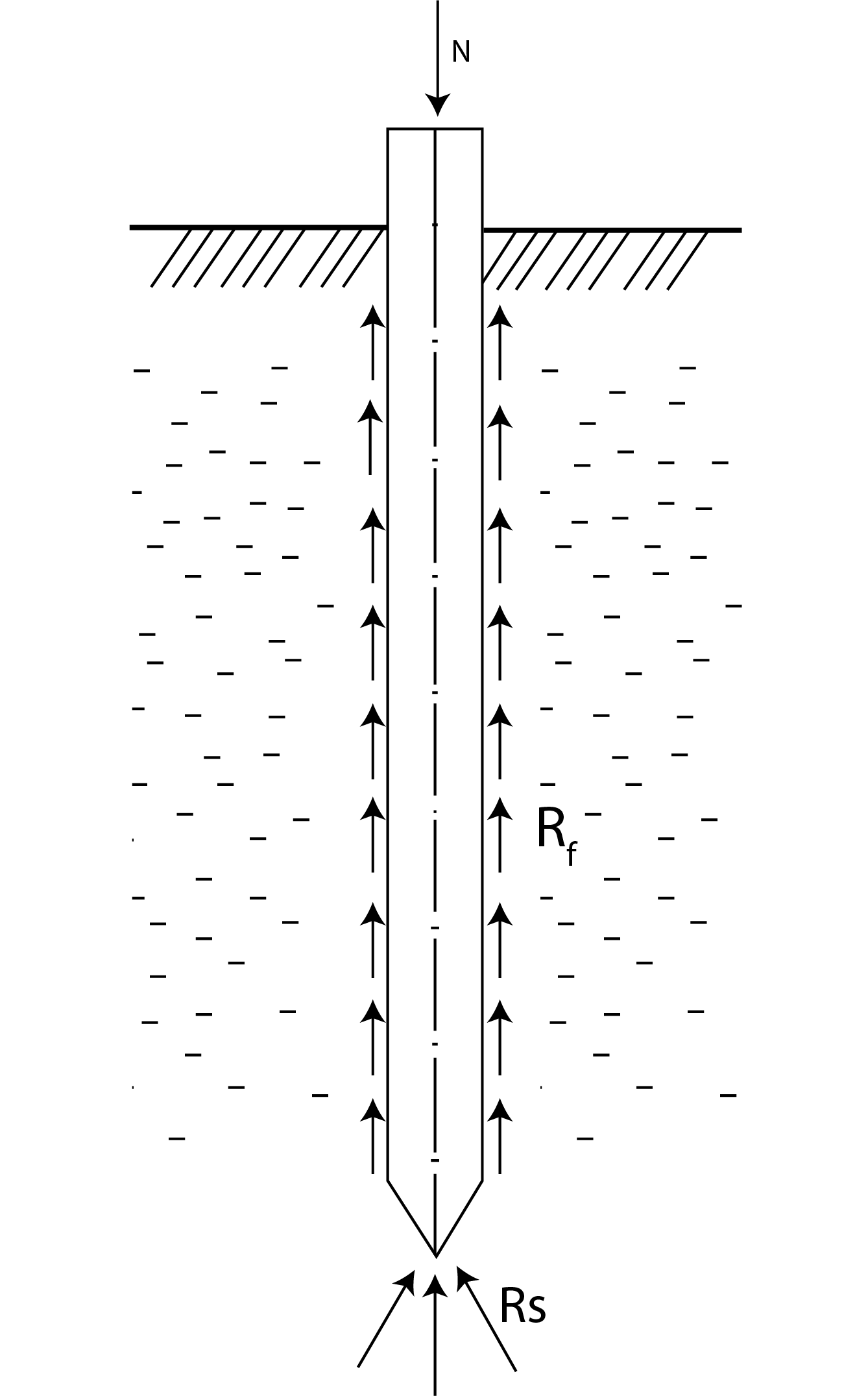
The length of the pile is established so that, through the combined effect of the friction on the side surface and the resistance in the base plane, the pile transmits to the ground the axial calculation load that belongs to him. It is recommended that the length of the large diameter drilled pile be determined according to the depth at which the practically incompressible layer meets. For piles with significant horizontal loads, the length of the pile is determined so as to ensure the necessary embedding in the field.
The depth of penetration of the pile into the load-bearing layer must be at least 2 d for piles with d <1.20 m and 1.5 d for piles with d ³ 1.20 m (d - diameter of the pile). If the load-bearing layer consists of a rock, it is allowed to embed at least 0.5 m after removing the layer of altered rock. Flaring at the base of the drilled pile is made only if the base penetrates in a layer with high cohesion, having resistance to compression with free lateral deformation (monoaxial compression) of at least 200 kPa when drilling in land and 300 kPa when drilling in water . Flaring is done in the form of a cone trunk, with a height at least equal to the diameter of the current section of the pile. It is recommended that the area of the widened base section does not exceedthree times the current section of the pile. In order to increase the load-bearing capacity of the drilled pile as well as to reduce the deformations due to the ground at the base, possibly weakened by the drilling operation, an injection can be provided at the base of the pile or along its lateral surface. For this purpose, the pipes through which the suspension is to be injected (usually cement milk) are embedded in the pile`s body, being lowered into the drilled hole together with the reinforcement housing. The recipe and injection technology are specified in the specifications.
3. Loads transmitted by the superstructure:
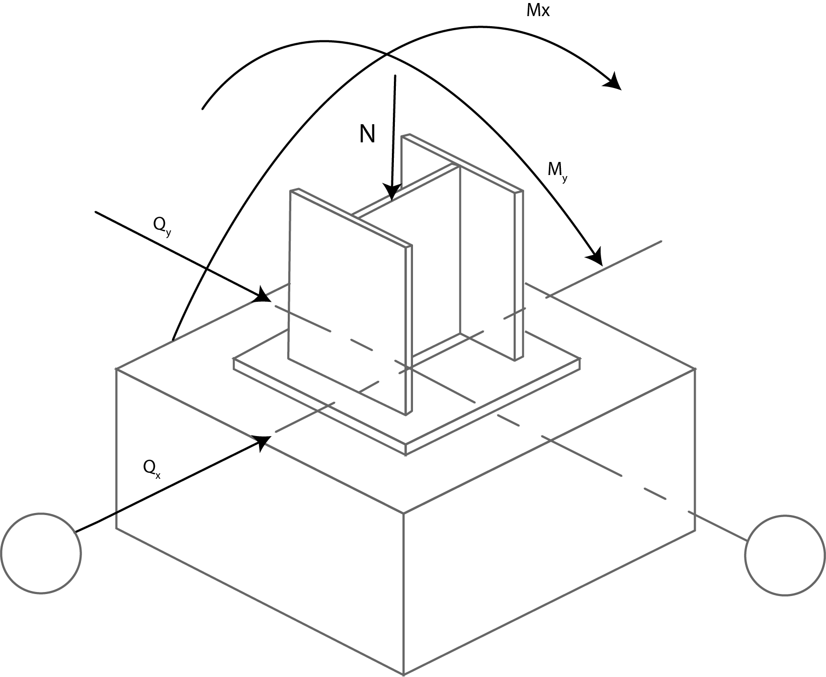
Axial force

KN
Bending moments:

KNm

KNm
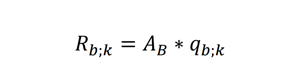
4. Pile-based resistance:
Pile base area:

For Pile with circular section

m 2
For Pile with square section

m 2
Drilling depth (Actual pile sheet)
m
Consistency index:

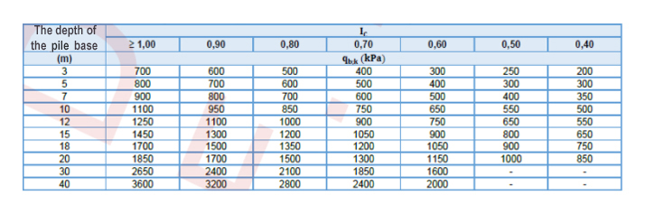
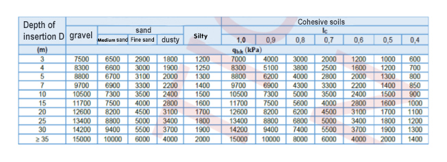
The characteristic value of the base pressure for drilled or displacement base piles on which it rests in cohesive soils (Annex A.7.1)

KN / m 2
Annex A.7.1. Characteristic values of pressure on the base, for displacement piles that rest on the base on cohesive soils , when the data on shear strength of the layer at the base of the pile are missing.
Characteristic pressure value based on prefabricated piles beaten or stuffed (Annex A.7.2)
KN / m 2
Annex A.7.2. Characteristic pressure values based on prefabricated piles
KN / m 2
KN / m 2
Annex A.7.1. Characteristic values of pressure on the base, for displacement piles that rest on the base on cohesive soils , when the data on shear strength of the layer at the base of the pile are missing.
Annex A.7.2. Characteristic pressure values based on prefabricated piles
Resistance calculation value based on the pile:
For Pile with circular section
KN
For Pile with square section
KN
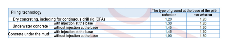
Partial coefficient of resistance based on piles introduced by drilling (Annex A.7.6)

Annex A.7.6 The values of the partial safety coefficient Y b or piles executed on the spot
Partial resistance coefficient based on piles introduced by pressing and beating (Annex A.7.8)
Table A.7.8. The values of the partial coefficients of resistance for prefabricated piles

The calculation value of the resistance based on the pile:
For Pile with circular section

KN
For Pile with square section
KN
5. Frictional resistance on the side surface of the pile:

For Pile with circular section

m
For Pile with square section

m
For layer {{index+1}}:
Layer thickness (What comes in contact with the pile)
l S,{{index+1}} = H S,{{index+1}} - D f
m
Consistency index:
I C, {{index+1}}
Average layer depth:
z {{index+1}} = D f + l {{index+1}} / 2
m
Characteristic value of lateral friction resistors
q s;k;{{index+1}}
KN / m 2
The characteristic value of the total frictional resistance on the side surface of the pile:
For Pile with circular section
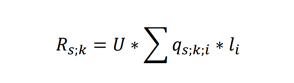
KN
For Pile with square section
KN
Calculation value of the total frictional resistance on the side surface of the pile for piles executed on the spot (Annex A.7.7)

Annex A.7.7. The values of the partial safety coefficient Ys for piles executed on the spot
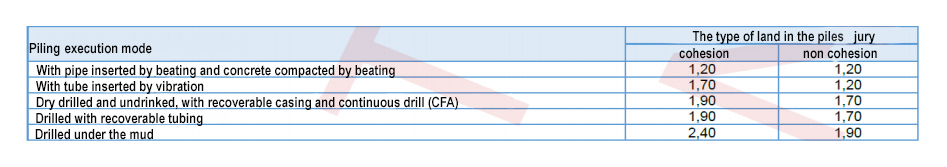
Calculation value of the total frictional resistance on the side surface of the pile for piles inserted by pressing and beating (Annex A.7.8.)
Table A.7.8. The values of the partial coefficients of resistance for prefabricated piles
Annex A.7.7. The values of the partial safety coefficient Ys for piles executed on the spot
Table A.7.8. The values of the partial coefficients of resistance for prefabricated piles
For Pile with circular section

KN
For Pile with square section
KN
6. Compressive load-bearing capacity of the isolated pile:
For Pile with circular section
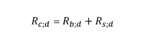
KN
For Pile with square section
KN
7. Determining the required number of piles
Axial force at the base of the column:
KN
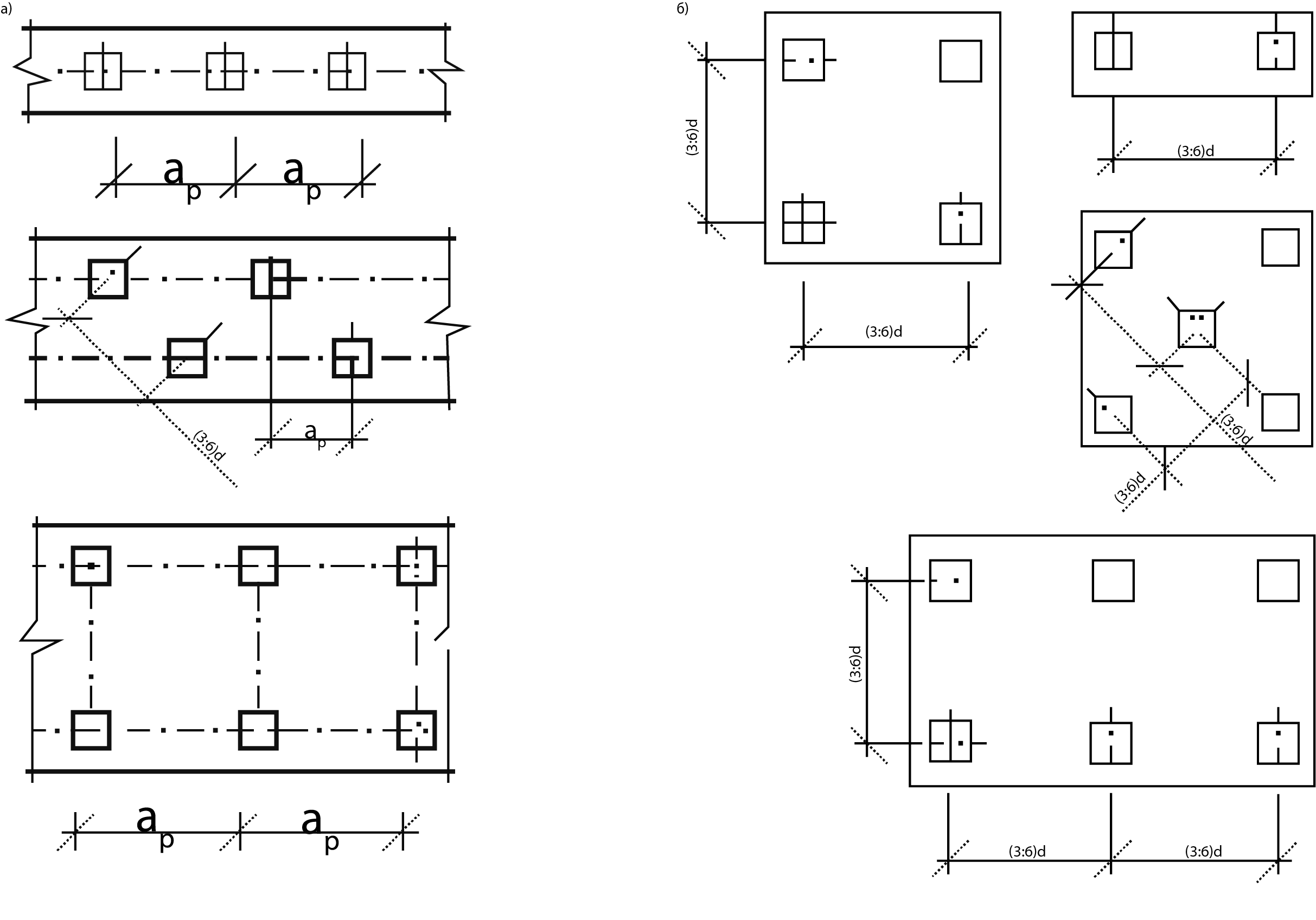
Distance between piles:
The minimum distance between the piles axes, measured in the field, is: 3d-in the case of piling or tapping piles and 2d + 0.03D-in the case of displacement piles (minimum recommended value)
Where:
d - diameter or section of the short side of the pile
D - the real file of the pile
For drilled or displacement piles:
For Pile with circular section
m
For crowded or beaten piles:
For Pile with square section
KN
Carrying capacity of the pile working in a group:
Coefficient of efficiency:
Coefficient of efficiency:

For Pile with circular section (Anexa A.7.7)

KN
Annex A.7.7. The values of the partial safety coefficient Ys for piles executed on the spot
For pile with square section for piles inserted by pressing and beating.(Anexa A.7.8.)
KN
Table A.7.8. The values of the partial coefficients of resistance for prefabricated piles
KN
Annex A.7.7. The values of the partial safety coefficient Ys for piles executed on the spot
KN
Table A.7.8. The values of the partial coefficients of resistance for prefabricated piles
Number of drilled or displacement piles:
For pilot with circular section
Number of piles, stuffed or beaten:
For Pile with square sectionReinforcement of piles is usually done with reinforcement housings consisting of longitudinal bars, stirrups or frets, stiffening rings and spacers. The concrete class must be at least C12 / 15 (Bc15) and will be correlated with the concrete class of the piles. The distance between the outer face of the marginal piles and the end of the screed must be at least 25 cm. The choice of concrete class, minimum cement dosage and type and size of aggregates are made in compliance with the provisions of SR EN 1536: 2004 and NE 012/1 : 2007. For piles located in lands with aggressive waters, the specific regulations must be taken into account when compiling the concreting recipe. The piles reinforcements are made, as the case may be, of steel type OB 37, PC 52 or S500.
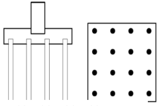
Design of pile groups
Normally the piles are installed in the group being secured at the top with a scraper. The column is positioned on the scraper so that the load from it is evenly distributed to the individual piles in the group.
The capacity of a group is obtained using the efficiency factor.
Pile group capacity = pile group efficiency * single pile capacity * number of piles. If in a group of piles there are 16 piles and the capacity of a single pile is 30 tons and the group efficiency is 0.9 then the capacity of the group of piles is 432 tons. (0.9 * 30 * 16). Clearly high efficiency of the group of piles is desirable, it depends on the distance between the piles. , the efficiency increases, only that the size of the eraser must be larger so the cost of the eraser also increases.
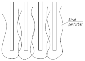
Earth disturbance during pile installation
When the piles are introduced, the ground around them is undisturbed. The disturbed ground has a lower resistance than the ground in its natural state. Some piles are introduced into the partially disturbed ground which causes a lower load-bearing capacity than in others. The disturbance of the ground caused by a pile affects the load-bearing capacity of the neighboring piles. The efficiency of the group can be improved by positioning the piles at a greater distance. In clay soils the shear strength is reduced due to the disturbance.
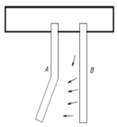
Earth disturbance during pile installation
When piles are introduced in a group, some piles may be bent due to the movement of the earth, this effect is more pronounced in clay soils. the introduction of the pile B can bend the pile A. Further this leads to a reduced capacity in the group.
The carrying capacity on the rod of the piles:
Piles based on peak carrying capacity may not be affected by other piles in the group. Piles founded in a very resistant layer or rock, when the piles do not depend on the lateral friction, an efficiency of group work can be used = 1
The pile is piled up in sandy soils:
When piles are inserted into sandy soils, the surrounding soil will be crowded. The dense soil tends to increase the lateral friction of piles. The group of piles placed in sandy soils may have a higher capacity than the efficiency of a pile. The compaction of the soil due to the introduction of the piles will be very small in clay soils.
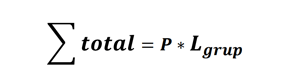
Total meters in the group of piles

Piles with circular section
Total meters in the group of piles with circular section
m
Piles with a square section
Total meters in the group of piles with a square sectionm
Enter the price for 1m of pile with round section *
P 1m
€/m
Price for 1m of pile with square section (materials, work and transportation included)
P 1m
€/m
The total cost of the group of piles with the round section
€
The total cost of the group of pilots with a square section
€